
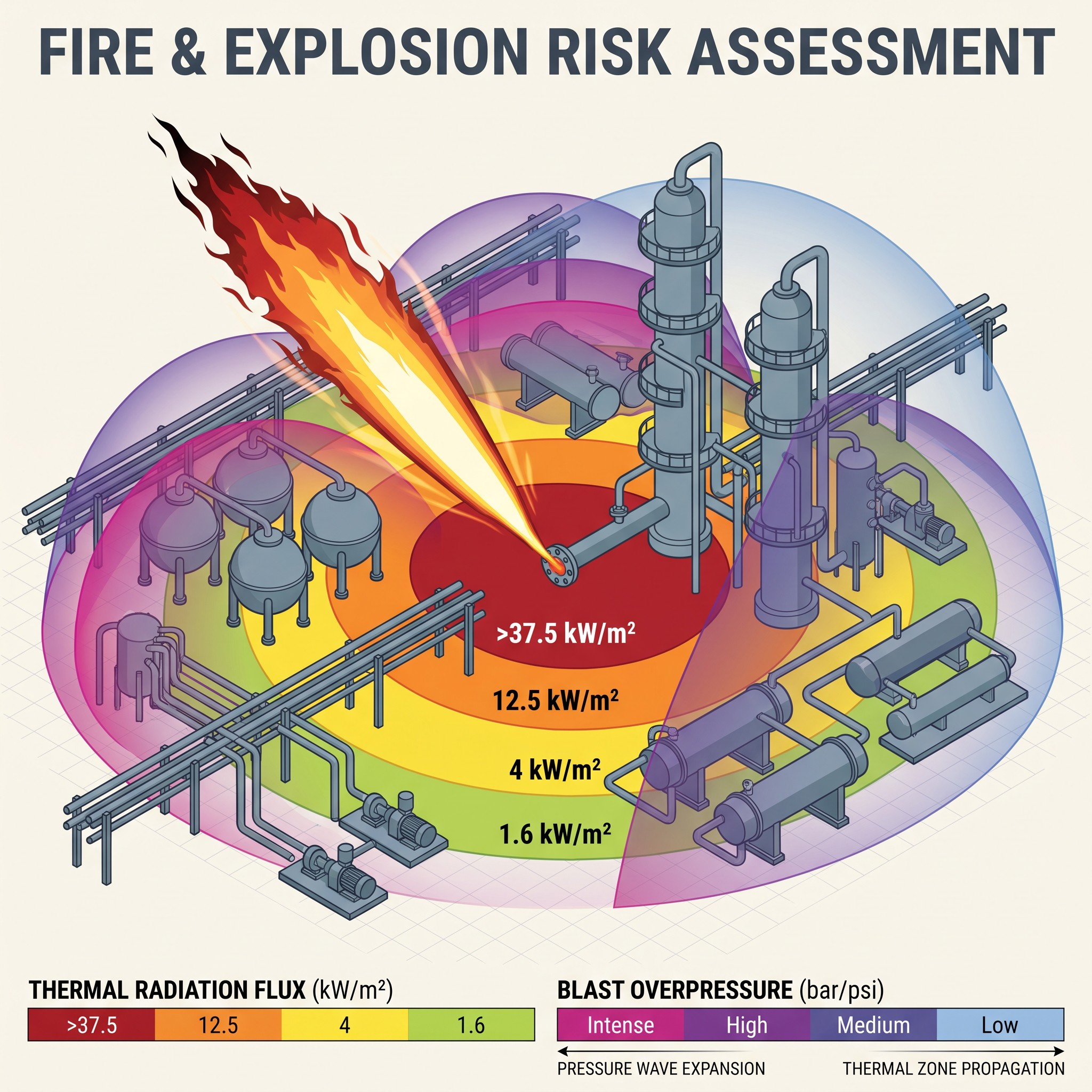
In oil and gas, petrochemical and chemical facilities, fire and explosion hazards are among the most critical safety concerns. A Fire and Explosion Risk Assessment (FERA) gives operators a structured, quantitative framework to identify, evaluate and control these hazards, protecting people, assets and the environment. It is used on both onshore and offshore processing facilities.
What is FERA?
FERA is a systematic risk assessment approach that identifies flammable materials and potential ignition sources, analyses the likelihood and consequences of fire and explosion events, and recommends preventive and mitigation measures that keep risk within tolerable limits. Understanding how flame radiation, thermal flux and blast overpressure interact with the plant layout is essential for designing effective physical barriers and optimising facility layout.
Key elements of a FERA
- Hazard identification. Flammables, ignition sources and containment.
- Risk analysis. Likelihood and consequence evaluation.
- Risk control. Engineering solutions, safeguards and emergency systems.
- Fire safety measures. Alarms, suppression systems and evacuation routes.
- Training and awareness. Personnel readiness and emergency drills.
- Regulatory compliance. Alignment with applicable codes and standards.
The six-step FERA methodology
Step 1: Hazard identification and scenario selection
A rigorous FERA begins with identifying potential loss-of-containment (LOC) sources across processing units, storage facilities and transport pipelines. Defining accurate failure modes early prevents critical exposure pathways being missed during detailed design.
- LOC source identification. Locating high-pressure equipment, flanges, valves, pumps and vessel connections with potential leak paths.
- Isolatable section definition. Grouping equipment by Emergency Depressurisation (EDP) and ESDV segmentation to calculate realistic inventory masses.
- Release category characterisation. Classifying releases as high-pressure gas jets, liquid pools, two-phase releases or volatile flash vapours.
- Credible ignition source mapping. Identifying hot surfaces, electrical equipment categories and fixed ignition points in hazardous zones.
A comprehensive hazard identification phase ensures no major accident scenario is omitted and lays the foundation for the modelling that follows.
Step 2: Release frequency and probability analysis
Once credible scenarios are established, Step 2 quantifies how often each could occur. Historical failure-rate databases are combined with site-specific parameters.
- Failure data integration. Applying recognised databases, such as OGP / IOGP and OREDA, for piping, valves and pressure vessels.
- Ignition probability modelling. Evaluating immediate versus delayed ignition based on fluid reactivity, release rate and proximity to ignition sources.
- Parts count analysis. Counting flanges, valves and instrument connections within each isolatable inventory to scale baseline leak frequencies.
- Event tree construction. Mapping escalation from the initial release to jet fires, pool fires, flash fires or VCEs.
Quantified frequencies let engineers separate frequent low-consequence events from rare catastrophic ones.
Step 3: Consequence and hazard modelling
With scenarios and frequencies defined, Step 3 models the physical effects. Specialised software is used to quantify thermal radiation intensity, jet flame reach, pool fire boundaries and blast overpressure contours across the facility layout.
- Thermal radiation modelling. Simulating jet and pool fires with tools such as PHAST and FlareSim to produce 4.7, 12.5 and 37.5 kW/m² radiation contours.
- Vapour cloud explosion (VCE) analysis. Assessing congestion and confinement to predict blast overpressure using TNT-equivalence or Multi-Energy methods.
- Toxic and flammable dispersion. Tracking cloud migration to find the lower flammable limit (LFL) extent and toxic exposure zones.
- Inventory depressurisation dynamics. Accounting for blowdown rates and inventory depletion over time to model transient fire and explosion severity.
High-fidelity modelling provides the physical boundary data needed to assess structural survivability and safe separation distances.
Step 4: Vulnerability and impairment assessment
Step 4 evaluates what the modelled radiation and overpressure do to plant assets and life-safety systems. The question is whether critical structures, safety-critical elements (SCEs) and emergency infrastructure can withstand exposure without escalating the incident.
- Structural vulnerability mapping. Comparing overpressure against design limits for control rooms, substations and pipe racks.
- SCE impairment. Evaluating the survivability of ESD valves, firewater systems and blowdown valves under heat exposure.
- Escape route and temporary refuge evaluation. Checking egress corridors and muster areas for radiant heat and smoke impairment.
- Domino effect analysis. Identifying neighbouring inventories at risk of secondary failure from flame impingement or structural collapse.
Understanding structural endurance prevents domino effects and keeps safety barriers functional during the critical emergency response window.
Step 5: Risk evaluation and criteria comparison
Step 5 combines scenario frequencies with vulnerability data to calculate overall fire and explosion risk. The results are compared with individual and societal risk acceptance criteria and the ALARP framework.
- Risk integration. Combining consequence exceedance curves with event frequencies to produce location-specific risk contours.
- ALARP framework evaluation. Comparing risk with tolerable and broadly acceptable criteria to highlight unmitigated high-risk areas.
- Escalation contour analysis. Identifying clusters where several impairment threats overlap.
- Regulatory compliance verification. Checking alignment with national and international standards such as NFPA, API and ISO guidance.
Comparing quantified risk with defined criteria supports objective decisions before the plant layout is frozen.
Step 6: Mitigation and risk reduction (drafted from the FERA overview post, please technical-review)
The final step turns findings into action. Where risk is not acceptable, the study recommends targeted layout modifications, passive fire protection (PFP), active fire suppression systems and structural blast reinforcement to reduce the chance of escalation.
Why FERA matters
A comprehensive FERA prevents catastrophic accidents, protects human life and assets, supports business continuity and reduces regulatory and financial risk. It ensures that physical hazards are accurately modelled, escalation potential is controlled and the facility layout meets robust safety criteria.
How EnTech can help
EnTech Engineering Solutions specialises in FERA, Quantitative Risk Assessment, consequence modelling, ALARP demonstrations and HAZID / HAZOP facilitation. Contact us at info@EnTech-Solution.com.